2008. 8. 1. 15:10ㆍJames/Papers
조영증강을 이용한 경부 자기공명 혈관 조영술에 관한 연구 :
서로 다른 세 가지 형태의 코일을 사용할 때 ;
(CP Neck Array, Head & Neck, CP Body Array)
- Abstracts -
Contrast-Enhanced 3D MR Angiography in Neck Vessels :
A Comparison of Three Different Types of Coil ; CP Neck Array, Head & Neck and CP Body Array.
H. NamKoong, R.T., K.H. Min, R.T., D.S. Kim, R.T., I.C. Song, Ph.D., K.H. Chang, M.D.
Department of Diagnostic Radiology, Seoul National University Hospital, Korea
Introduction: Circularly Polarity (CP) neck array and head & neck coils have been generally used in contrast-enhanced 3D MR Angiography (MRA) to show neck vessels, but were limited to depict whole neck vessels from aortic arch to carotid bifurcation. In this paper we used CP body array coil together with supplementary device for contrast-enhanced 3D MRA images in neck vessel study. The aim of this study is to compare contrast-enhanced 3D MRA images obtained with the three different types of coil.
Materials and Methods: Twenty-five patients (male: 11, female: 14, mean age: 55.2) were examined contrast-enhanced 3D MRA for neck vessels, using one of three different types of coil (CP neck array: 7, head & neck: 7, CP body array: 11) at 1.0T Impact-Expert (VB31b, Siemens, Germany). In CP body array coil, the new supplementary device, which was made of acryl, was used for a patient safety. For contrast-enhanced 3D MRA, FISP 3D (Fast Imaging Steady-state Precession) pulse sequence was used in the all three different types of coil, and the scan parameters were as follows: TR/TE: 5.4/2.3ms, 300 flip angle, 1 slab of 80mm thickness, 20 partitions, coronal or oblique orientations, 161*256 matrix, 450mm FOV, 390Hz/pixel bandwidth, 1 acquisition, 10 sec acquisition time. A total of 15-20ml of contrast media was injected by manually at an approximate rate of 2 ml/sec. Scanning was commenced 12-14 sec after start of contrast media injection. All contrast-enhanced 3D MRA images were obtained by MIP (Maximum Intensity Projection) after subtracting pre- from post-contrast images. After the signal intensities of the aortic arch, innominate and common carotid arteries, and background were measured, the SNR (ROI_intensity / background_intensity) and the CNR (ROI_intensity background_intensity / background_intensity) were calculated, and compared among contrast-enhanced 3D MRA images from three different types of coil.
Results:
The signal intensity at the aortic arch were significantly lower than that of other two regions in case of CP neck array and head & neck coils. However, the signal intensity in use of the CP body array coil showed smaller variation over three regions, and higher SNR was noted in the CP body array coil than in other two different types of coil. The CP body array coil showed smaller variation in CNR, but lower CNR than the head & neck coil.
Conclusion: It is suggested that the CP body array coil may be superior to the CP neck array and head & neck coils in depicting whole neck vessels from the aortic arch to the common carotid artery.
I. 목 적.
기존의 자기 공명 혈관 조영상 (MR Angiography)은 주로 TOF(Time of Flight)와 PC(Phase Contrast) 방법으로 영상을 구성하였다. 그러나 근래에 들어서 강력한 경사 자계 (Gradient field strength)와 정밀한 자기 균일도 (homogeneity)를 바탕으로 한 초고속 영상 기법이 소개되면서, 이를 MR Angiography에 응용하게 되었다. 그 원리는 강한 T1 강조 영상에서 조영제를 고속으로 주입하게 되면 조영제가 혈관속을 흐를 때, 이에 의해 혈관의 T1 시간이 매우 짧아져 영상에서 혈관의 신호만 증강되게 된다. 이러한 조영증강 혈관 조영술 (Contrast-Enhanced MR Angiography)은 매우 짧은 검사 시간을 장점으로 대동맥, 복부동맥, 사지의 혈관 영상 등에 폭넓게 응용되고있는 추세이다.
특히, 경부의 혈관계를 보기 위한 통상의 Contrast-Enhanced MR Angiography는 검사에 사용되는 경부 코일 (CP neck array coil) 과 두경부 코일 (head & neck coil)을 사용할 때 코일의 특성상 대동맥궁(aortic arch)에서부터 내경동맥(internal carotid artery)까지의 전체적인 경동맥 묘사에 어려움이 있었다. 이에 이번 실험은 이러한 어려움을 감소시키는 방법으로 체코일 (CP body array coil)을 경부에 사용하고자 하였으며, 이를 위해 보조 지지대를 직접 제작하여 환자의 안전과 편안함을 유지하면서 경부 혈관 조영 영상을 얻은 후, 다른 형태의 코일인 경부코일과 두경부 코일에서 얻은 경부 혈관 조영 영상과 비교, 평가하였다.
II. 실험방법 및 재료.
1997년 1월부터 6월까지 25명 (남자 11명, 여자 14명, 평균나이 55.2세)의 뇌혈관 영상을 의뢰한 환자를 대상으로 각기 다른 세 가지 코일인 CP neck array 코일 (7명)과 head & neck 코일 (7명)을 그리고 CP body array 코일 (11명)을 사용하여 Contrast-Enhanced MR Angiography를 1.0T Impact-Expert (VB31b, Siemens)에서 얻었다. CP body array coil을 사용할 때는 코일이 환자의 두경부와 접촉되는 것을 방지하면서 환자의 안전 및 사용의 용이성을 위하여 아크릴로 직접 제작한 보조 지지대를 사용하였다.(그림1.)
사용한 pulse sequence는 FISP3D (Fast Imaging Steady-State Precession)로 조건은 TR/TE: 5.4/2.3ms, flip angle: 300, number of slab: 1, slab thickness: 80mm, number of partitions: 20, effective slice: 4mm, orientation: coronal, oblique coronal, matrix: 161 (101;rectangular 5/8)![]() 256 (read oversampling), number of acquisition: 1, number of measurement: 3, band width: 390Hz/pixel, acquisition time: 10sec로 하였고, FOV는 300mm(CP neck array, head & neck), 450mm(CP body array)로, 위상 변이 방향 (phase encoding direction)은 left에서 right (CP neck array, head & neck)와 head에서 feet (CP body array)로 하였다.
256 (read oversampling), number of acquisition: 1, number of measurement: 3, band width: 390Hz/pixel, acquisition time: 10sec로 하였고, FOV는 300mm(CP neck array, head & neck), 450mm(CP body array)로, 위상 변이 방향 (phase encoding direction)은 left에서 right (CP neck array, head & neck)와 head에서 feet (CP body array)로 하였다.
이중 검사시간을 최대한 줄이기 위하여 rectangular FOV를 5/8로 사용하였으며, 검사 단면은 혈관의 주행과 평행하게 coronal 혹은 oblique coronal로 하였다. subclarvian artery를 보기 위해 위상변이 방향을 head에서 feet쪽으로 주었다. 또한 동맥과 정맥을 구분하여 영상을 얻고자 3번의 검사를 연속해서 하였다.
조영제는 15![]() 20ml를 2
20ml를 2![]() 3ml/sec의 속도로 수동 주입하였으며, 검사는 조영제 주입 12
3ml/sec의 속도로 수동 주입하였으며, 검사는 조영제 주입 12![]() 14초 후에 시작하였다. 모든 영상은 조영제 주입 후, 3회 연속으로 영상을 얻었으며, 이 조영제 주입 후 얻은 3개의 영상에서 조영제 주입 전에 얻은 영상을 감(subtraction)하여, MIP(Maximum Intensity Projection)처리 하였다.
14초 후에 시작하였다. 모든 영상은 조영제 주입 후, 3회 연속으로 영상을 얻었으며, 이 조영제 주입 후 얻은 3개의 영상에서 조영제 주입 전에 얻은 영상을 감(subtraction)하여, MIP(Maximum Intensity Projection)처리 하였다.
평가는 먼저, aortic arch와 innominate artery 그리고 common carotid artery에서 각각의 신호 강도를 모든 영상에서 구하였고, back ground 신호강도는 가능한 ROI를 크게 하여 noise 및 subtraction의 영향을 많이 반영하고자 하였다. 이후, SNR(ROI_ intensity / back ground_intensity)과 CNR(ROI_intensity - back ground_intensity / back ground_intensity)을 계산하여 각 코일의 특성을 비교하였다.
그림1. 보조 지지대
III. 결과.
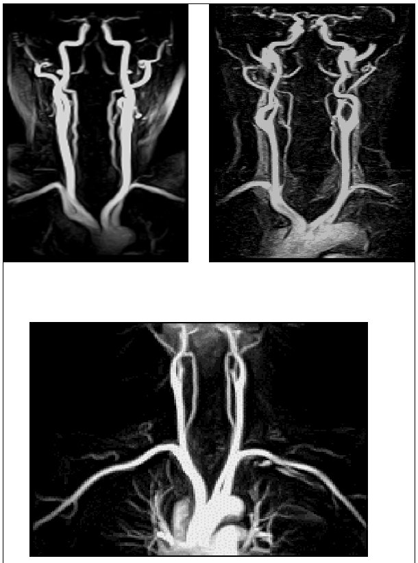
그림 2. 각 코일에서의 첫 번째 (1st. Phase) MR Angiography.
|
coil ROI |
Signal Intensity |
SNR. |
CNR. | ||||||
|
AA. |
IA. |
CCA. |
AA. |
IA. |
CCA. |
AA. |
IA. |
CCA. | |
|
CP neck array |
63.0 |
94.8 |
159.9 |
3.0 |
4.7 |
8.7 |
62.0 |
93.8 |
158.9 |
|
head & neck |
211.5 |
248.3 |
325.2 |
3.9 |
5.0 |
7.9 |
202.6 |
252.9 |
395.8 |
|
CP body array |
177.7 |
179.1 |
155.5 |
11.2 |
10.9 |
9.2 |
176.8 |
178.1 |
154.5 |
(AA: Aortic Arch, IA: Innominate Artery, CCA: Common Carotid Artery.)
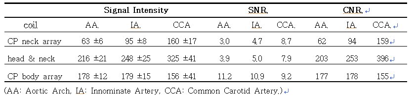
표 1. 각 부위의 신호강도 및 SNR.과 CNR.
그림2.와 표1.에서 보면, 먼저, 신호강도는 CP neck array coil에서 aortic arch, innominate artery, common carotid artery가 각각 63.0![]() 5.7, 94.8
5.7, 94.8![]() 7.8, 159.9
7.8, 159.9![]() 17.3이였고, head & neck coil에서는 각각 211.5
17.3이였고, head & neck coil에서는 각각 211.5![]() 20.8, 248.3
20.8, 248.3![]() 24.5, 325.2
24.5, 325.2![]() 41.3으로 나타나 aortic arch가 common carotid artery에 비해 상대적으로 CP neck array coil은 약 60%, head & neck coil은 35%의 신호감소를 보였다. 그러나 CP body array coil은 177.7
41.3으로 나타나 aortic arch가 common carotid artery에 비해 상대적으로 CP neck array coil은 약 60%, head & neck coil은 35%의 신호감소를 보였다. 그러나 CP body array coil은 177.7![]() 11.5, 179.1
11.5, 179.1![]() 14.9, 155.5
14.9, 155.5![]() 41.1을 보여 aortic arch가 common carotid artery에 비해 오히려 14% 높은 신호강도를 보였다.
41.1을 보여 aortic arch가 common carotid artery에 비해 오히려 14% 높은 신호강도를 보였다.
두 번째 SNR을 살펴보면, CP body array coil은 aortic arch, innominate artery, common carotid artery가 각각 11.2, 10.9, 9.2로 모든 부위에서 비슷한 값을 보인 반면, CP neck array coil과 head & neck coil은 각각 3.0, 4.7, 8.7과 3.9, 5.0, 7.9를 보여 aortic arch가 common carotid artery에 두배 이상 낮은 수치를 보였다.
세 번째 CNR은 aortic arch, innominate artery, common carotid artery가 202.6, 252.9, 395.8을 보인 head & neck coil이 가장 높은 값을 보였고, CP body array coil은 176.8, 178.1, 154.5를 CP neck array coil은 62.0, 93.8, 158.9를 보여 가장 낮은 값을 보였다.
또한, 그림3에서 보듯이 10초의 검사시간으로 세 번 연속해서 영상을 얻어 동맥, 동맥과 정맥, 정맥의 혈관 영상을 구분해서 얻을 수 있었다.
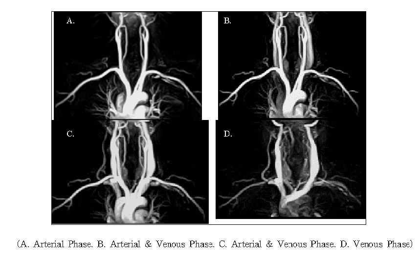
그림 3. 각 검사 시간대별 MR Angiography.
IV. 고찰 및 결론.
Contrast-Enhanced MR Angiography는 최대의 관점이 조영제가 보고자하는 혈관을 흐를 때 data를 수집, 영상화하는 것이다. 그러므로 조영제 주입 시작 시간과 관심 혈관이 조영 증강되는 싯점을 계산, 검사 시간을 정하는 것이 매우 중요하다. 이에 이번 실험에서는 본 실험에 앞서 5명의 환자를 대상으로 IV line을 통해 수동으로 15![]() 20ml를 7
20ml를 7![]() 10초 동안 주입하였을 때, common carotid artery가 평균 18
10초 동안 주입하였을 때, common carotid artery가 평균 18![]() 20초, jugular vein이 평균 25
20초, jugular vein이 평균 25![]() 27초 사이에 조영 증강되는 것을 확인하고, 이를 근거로 하여 15
27초 사이에 조영 증강되는 것을 확인하고, 이를 근거로 하여 15![]() 20ml의 조영제를 약 2
20ml의 조영제를 약 2![]() 3ml/sec의 속도로 주입하고 이어서 생리 식염수 10ml를 같은 속도로 밀어 넣었다. 그리고 검사 시작 시간은 가능한 동맥과 정맥을 구분하고자 정맥이 약 25초부터 조영 증강되므로, 이전에 동맥 검사가 끝나도록 조영제 주입 시작 12
3ml/sec의 속도로 주입하고 이어서 생리 식염수 10ml를 같은 속도로 밀어 넣었다. 그리고 검사 시작 시간은 가능한 동맥과 정맥을 구분하고자 정맥이 약 25초부터 조영 증강되므로, 이전에 동맥 검사가 끝나도록 조영제 주입 시작 12![]() 14초 후에 시작하였다. 물론 실험 대상 인원이 5명으로 적고, 수동 주입으로 인한 주입 속도의 정확성이 떨어지긴 하였어도, 이를 바탕으로 한 모든 영상에서 관심 혈관을 묘사하는데는 어려움이 없었다. 또한, 정맥 혈관만 묘사하기 위하여 세 번째 검사에서 첫 번째 검사를 감(subtraction)하여 동맥 혈관을 제거한 정맥 혈관만의 영상도 얻을 수 있었다.(그림3. D.)
14초 후에 시작하였다. 물론 실험 대상 인원이 5명으로 적고, 수동 주입으로 인한 주입 속도의 정확성이 떨어지긴 하였어도, 이를 바탕으로 한 모든 영상에서 관심 혈관을 묘사하는데는 어려움이 없었다. 또한, 정맥 혈관만 묘사하기 위하여 세 번째 검사에서 첫 번째 검사를 감(subtraction)하여 동맥 혈관을 제거한 정맥 혈관만의 영상도 얻을 수 있었다.(그림3. D.)
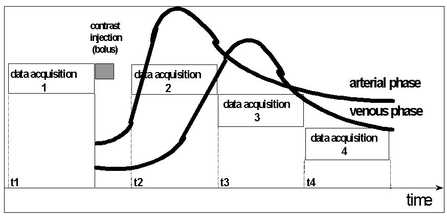
그림4. 검사시간 및 조영제 주입시간 도표.
모든 코일은 코일 크기에 알맞은 신호 수집 대역이 설정되어 있고, 본 실험에서 사용한 코일은 CP neck array, head & neck, CP body array 순으로 신호 수집 대역이 넓게 되어 있어 결과에서와 마찬가지로, CP body array 코일이 넓은 부위를 신호 감소 없이 일정하게 신호 수집이 가능하였고, head & neck, CP neck array 코일 순으로 신호 수집 대역이 좁은 것을 알 수 있었다. 반면, 신호강도와 공간 분해능 (spatial resolution)을 비교하면, head & neck 코일에서의 신호 강도가 CP body array에서의 신호 강도 보다 모든 부위에서 높게 나타났고, pixel 크기도 1.79![]() 1.17로 2.78
1.17로 2.78![]() 1.76인 CP body array 코일 보다 작아 공간 분해능이 더 높았다. 그러나 head & neck 코일은 aortic arch가 common carotid artery에 비해 상대적으로 35%의 신호 감소를 보여 혈관전체의 신호 균일성이 CP body array 코일 보다 떨어지는 것을 알 수 있었다.
1.76인 CP body array 코일 보다 작아 공간 분해능이 더 높았다. 그러나 head & neck 코일은 aortic arch가 common carotid artery에 비해 상대적으로 35%의 신호 감소를 보여 혈관전체의 신호 균일성이 CP body array 코일 보다 떨어지는 것을 알 수 있었다.
종합해 보면, 신호강도와 CNR의 상대적 비교는 head & neck 코일이 우수했으나, SNR과 전체 혈관의 신호강도 및 CNR의 균일도는 CP body array 코일이 우수하게 나타났다. 이는 임상에서 일반적으로 carotid bifurcation 부위의 경부 혈관을 보기 위한 검사는 CP neck array 코일이나 head & neck 코일이 바람직하며, aortic arch를 포함한 전체 경부 혈관 검사는 CP body array 코일을 이용하는 것이 더 나은 Contrast-Enhanced MR Angiography를 얻을 수 있을 것 같다.
참고 문헌.
1.Vogl TJ, Hoffmann Y, Juergens M, et al. [Eeperimental evaluation of contrast medium enhanced high resolution MR angiography in the animal model. Gd-DTPA comppared with Gd-DTPA-polylysine]. Radiologe 1996;36(3):254-62.
2. Tweedle M.F. et al Magn. Reson. Med. 1991,22,191.
3. M. Boos, K. Scheffler, J. Seelig. G. Bongartz. [First pass contrast-enhanced MR angiography timming and contrast agent concentration in carotid imaging]. ISMRM fifth scientific meeting 1997;volume 1:204.